Building the Bench
This is the first in a three part series on building and using a testing bench for ICS systems. In this series we will build a physical test bench, review program logic to find flaws, perform manual exploitation of commonly used ICS protocols such as Modbus, then develop malware to automatically exploit the bench to cause flooding.
Whether it’s in the water we drink, the medicines we take, or the electricity we use to read blog posts on the internet, Industrial Control Systems (ICS) are part of our daily lives. There’s so much that relies on these systems, you’d like to assume they’re engineered and tested to guard against cyberattacks. You’d be wrong.
Why aren’t our systems prepared for attacks? This is a tricky question. The systems running our critical infrastructure contain equipment 20+ years old. It’s not uncommon to see equipment 50+ years old which would require a full system revamp due to dependencies, and can easily cost millions.
Another factor? Cybersecurity specialists tend to focus on IT systems, applying the concepts they have learned for that environment. It can be shockingly difficult to explain the logistical reasons an OT environment may have 10+ embedded Windows XP servers, and why they cannot simply be upgraded or patched. A common example of this is present in Human-Machine Interfaces (HMI) where the embedded systems both have vomited memory which prevents upgrades to more resource intensive OS and require applications written in the early 2000’s to interface with a piece of technology.
But the largest issue for testing is a skillset gap. Testing in ICS environments means working on systems where the wrong packet could cause injuries to life or limb. Programmable Logic Controllers (PLC), especially older models, might have extremely limited memory resources which could result in a Denial-of-Service (DOS). They might also crash should they accept a packet they cannot interpret. These operational impacts can be instantaneous, preventing timely manual intervention after they begin. Most organizations don’t have the risk appetite for such testing, and even fewer work to acquire the knowledge necessary to assess these networks. As such, very few penetration testers actively perform testing within these environments. This means that even those critical infrastructure providers who might wish for testing to be done may find it impossible to find a tester who can provide a valid assessment without operational impacts.
I have been developing the internal network ICS penetration testing program here at Rapid7. During this process, I found that while there were many highly valuable resources available for training online, the amount of organizations sharing this knowledge appeared to be much smaller than one would expect given the criticality of these systems. For example, I have yet to discover a good online resource that provides knowledge on how to assemble and use a physical testing environment for penetration testing and malware development. While digital simulations such as Factory.io do exist, when you are training to deal with physical systems I believe it is important to have some experience with them in a hands-on manner. In addition, in building a test environment for yourself, a greater understanding of the system and its vulnerabilities can be gained.
These test systems, once built, additionally allow for simulation of program logic for PLCs. This allows for flexibility during a penetration test, and allows testing to occur in a safe environment where operational impacts would not be a concern. Otherwise, necessary avoidance of activities which would result in operational downtime might leave gaps in an organization’s security.
I would like to contribute to the knowledge pool and help bridge some of the gaps I felt when learning for myself. The goal of this series is to promote free sharing of knowledge in relation to ICS cybersecurity and penetration testing to help raise the skill floor and ensure organizations can receive proper testing to help protect our most critical systems.
Some Assembly Required
Note: As a disclaimer: While I will not be diving deep into electrical knowledge here, I would highly recommend searching for some basic knowledge on electricity and safety before attempting any of this at home. Even at low voltages, current flowing through your body can be fatal depending on several factors. In addition, for this buildout I will be working with water. Additional care must be taken when working with electricity around water. The typical resistance of human skin within dry environments can range from 1,000 to 100,000 Ohms, which might protect you from shocks which would otherwise be dangerous. However, wet skin has much less resistance and may result in dangerous current in otherwise similar circumstances. Please proceed with caution, use proper personal protective equipment, and prioritize safety at every step. Rapid7 does not assume responsibility for any injury or damage resulting from attempts to replicate this setup.
First, let’s look at what we might like to make. One of the easiest projects to start with is a system that moves something, so for our purposes we will use a simple gravity well and valve to pump water through some tubing to a container. To add some components and complexity, we’ll add a pump to the system to move the water out of the first container to a separate container. This will simulate a very basic process environment. We can additionally add some lights to denote the status of the process in its loop.
Supplies Gathered for Bench
Now that we know what we are making, we are going to need a controller. You can decide the PLC you would like to use to match budgetary limitations and the protocols you wish to test. Not all PLCs will allow you to test all protocols, so ensure you get the correct one for your use case. In my example I am choosing an Allen-Bradley Micro820. While the pricing on this might be higher than your budget, it does support several commonly-used protocols. Additionally, Rockwell provides the Connected Components Workbench software used for programming the device for free, which I found to be a nice plus. You will also need a power supply for your testing, for this I’ll be using a simple bench power supply that can go up to 32 Volts DC.
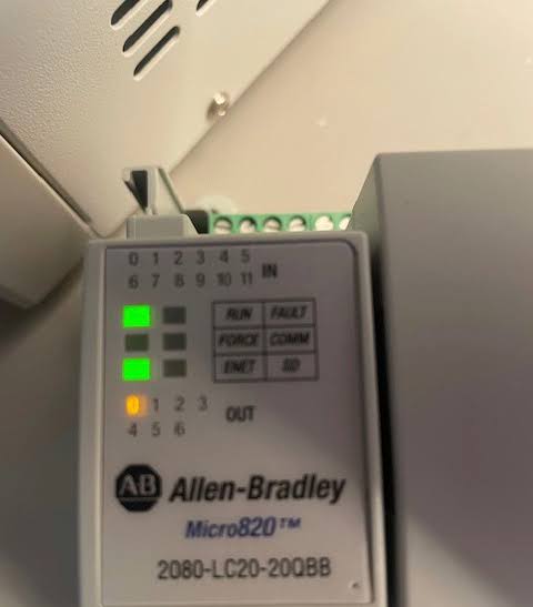
Micro820 Programmable Logic Controller in Operation
Next we will look at acquiring components and testing them for functionality and safety. Before getting components, we need to know what input voltage we will need to work with. The Micro820 is a great learning PLC as it runs off of 24 Volts DC. Lower voltage gives more room for mistakes should they occur, both for personal and component safety.
I ordered a stoplight that also runs off of 24v DC to function as our signal to show process status. Upon receiving a new component, the first thing you should do is test its functionality and readings to ensure it was correctly wired and advertised. You don’t want to jump right to 24v if a component can only take 12v - that is a good way to burn something out.
What I am going to show next is a methodology that you can apply to all components you wish to use, though we will only go through it for the stoplight.
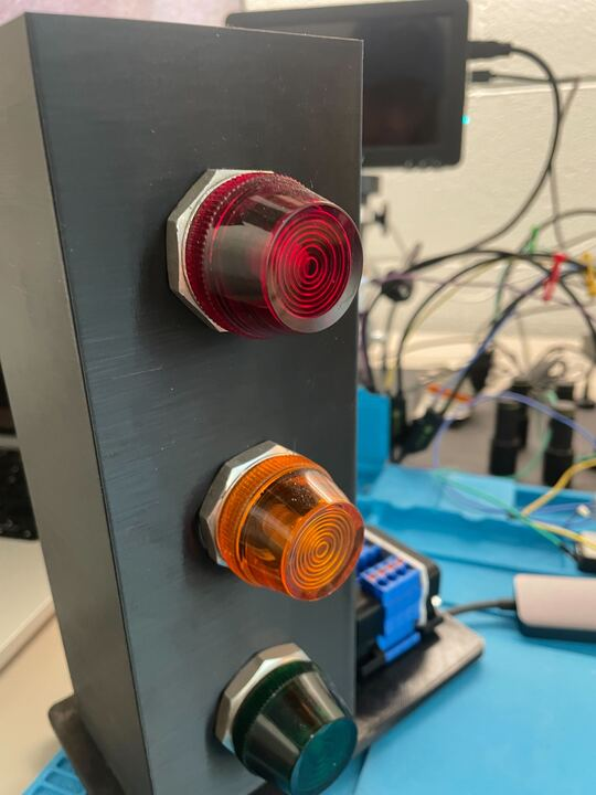
Stoplight Bench Component
The next step is to open it up and review the wiring. Here you can see the white and blue line leads into the bottom light, then runs as a black wire in series through the others. Meanwhile the blue lines going to the other terminals on the lights appear to be wired in parallel. You don’t need to fully be able to identify those right now, but recognizing that the setup implies that the blue and white line is the common while the blue lines are input is important.
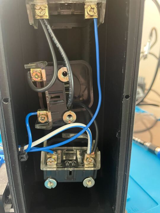
Internal Wiring of Stoplight
Next we want to make sure that we can identify A: where the wires connect in the terminal blocks, and B: that the circuits are all complete and there are no unexpected breaks. To this end we will use a multimeter and perform continuity checks from the input side of the terminal blocks to the end of each light.
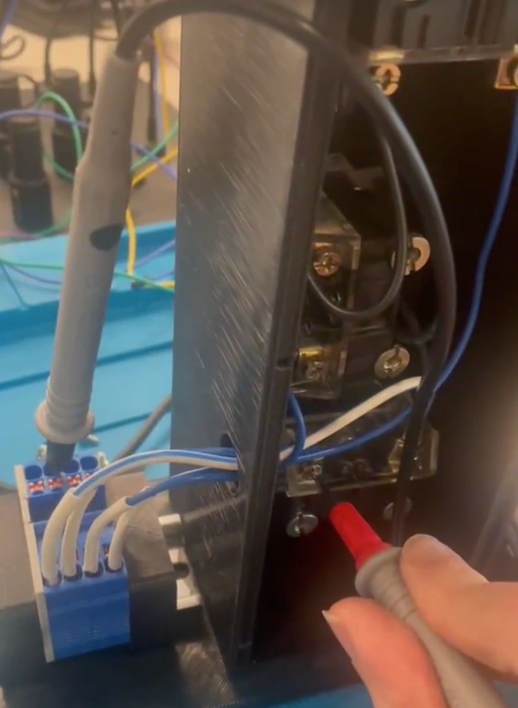
Continuity Tests
Next we will check the pilot lights to ensure that we don’t provide too much power and blow them out. By taking them out we confirm that they are Allen Bradley 800T-P16 pilot lights. They are rated for up to 120V AC and a high enough amperage rating that nothing we can do with this power supply will burn them out, meaning they are safe for use without any further modifications to the system.
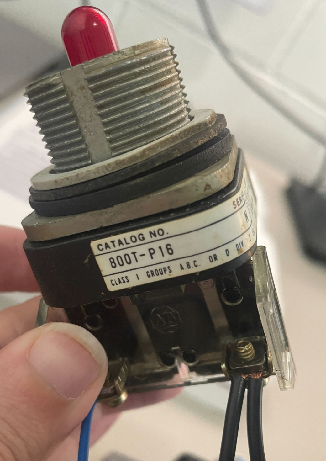
Pilot Light Model Discovery
Now we can proceed to wiring. I suggest using traditional DC wiring standards to denote the common as black. As a note, AC standards are different and result in black being the ‘hot’ wire – please don’t get that confused! The inputs on our Micro820 are sourcing, which means they supply power. This will be important to know later, but for now remember this: power flows into each line individually and flows out through the shared common. I use my bench power supply to connect to all three lights in parallel, and confirm that they properly light at 24v DC, concluding testing of this component.
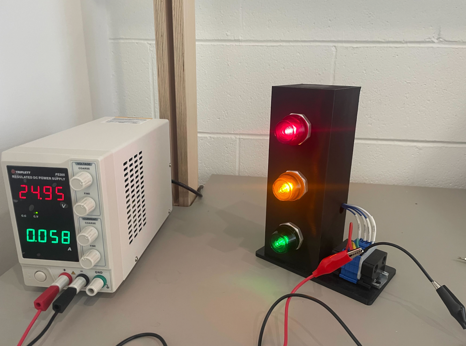
Fully Confirmed Functionality for Stoplight
We proceed with each of the components in a similar fashion to ensure they all function correctly and at the advertised voltages. It’s possible when planning your test bench you run across components that need a lower voltage. In those cases, a simple buck converter can be used in-line to step down the output voltage to avoid malfunctions in the component.
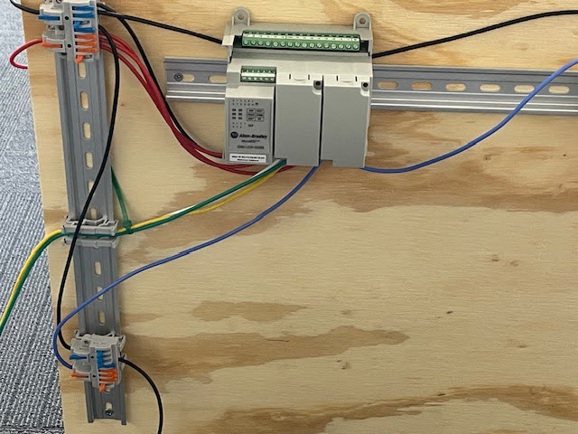
Once everything is tested, it is time to mount and wire. For a simple project like this, I used a cheap 2x2 square of plywood, though you can use anything you feel is sufficient to hold and maintain the weight mounted to the board. Make sure you properly position your supports so that it does not fall forward, as the board might be top-heavy.
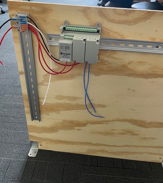
Mounted and Wired PLC
I’d like to additionally take a moment to talk about terminal blocks and wire management. (I could do a whole blog post on this, and perhaps I will soon.) Your PLC will only have so many connectors available on its block, and you don’t want to cause a short by trying to cram too many wires into one slot. Splicing terminal blocks are great for relaying common connections to all of your components while keeping connections at the PLC itself minimal. In addition, many of them can be mounted to the DIN rail, allowing for a very smooth and cohesive flow of wires compared to what you might otherwise have.
Wires Connected to Terminal Blocks
While wiring pieces together, you will want to ensure that you only expose the amount of wire needed to make a connection. Any additional exposure and you risk causing a short should a stray strand of another wire touch any hot wire. In addition, make sure that your wire is correctly rated for the current or you might be at risk of fire. For this project, I found 16 gauge wire to be more than sufficient.
As I will be connecting power through my bench supply I need to design a way to both keep the power connections themselves away from all other components, wires, and water systems and ensure that there is no chance of a short circuit. To solve this in a simple fashion, I lead the wires around to the back of the panel, where they are the only connections. I then connect the bottom input connection through a terminal block while relaying common through yet one more block, lengthening the distance between the leads. This helps to minimize the risk of a short should either wire disconnect.
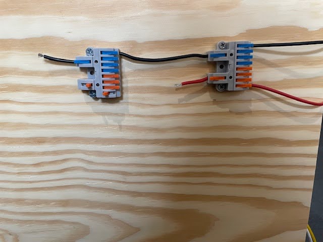
Input Power System
Now we can look at the water systems. For any tubing or components you connect, you will want to ensure that any National Paper Taper (NPT) threads are properly wrapped with Teflon Tape and clamped. If you do not do this, your connectors will leak under pressure. While the designed system here separates wires from water systems well, water near live wires would substantially increase risk and should be minimized. Always try to separate your electrical systems from any other components where possible to minimize risk of unintended interactions.
When working with a new type of system, be it pneumatic, water pressure, or electrical, I’d highly recommend doing some trades research to get knowledge from those who work with the system on a deeper level. It will greatly reduce the number of trips you need to make to your local hardware store!
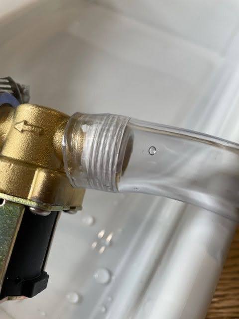
Teflon Tape Applied to NPT Threads
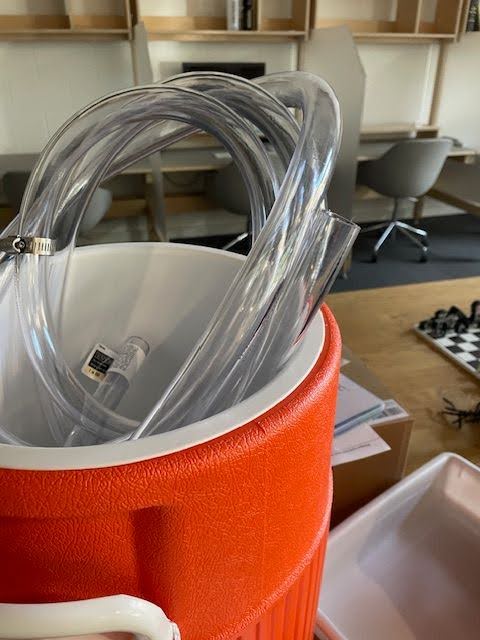
Before connecting any water components, I recommend doing an isolated test of water flow to ensure no unexpected leaks occur. Doing so helps to ensure that you don’t run into a cascading failure with water flowing onto your board, components, or bench power supply.
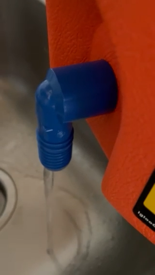
Isolated Leakage testing
Once everything is connected, the system is ready for programming and operation and the initial test bench is complete. This system is easily scalable once you understand how it operates, making it easy to work with someone else’s logic and add various sensors and components to get physical simulation of exploitable logic flaws at a much smaller and safer scale.
In the next article, we will discuss how to program the PLC, logic flaws commonly seen in the programs, and manual exploitation of the system. The article following that will discuss development of malware which can exploit the vulnerabilities in our system.
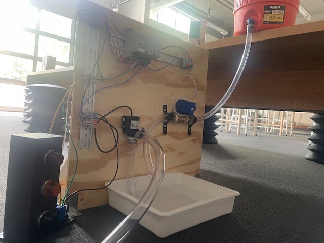
Completed Bench Assembly